Electromagnetic Induction and AC for NEET 2026
Electromagnetic Induction and AC for NEET 2026: Master Concepts, Formulas & Problem‑Solving Tricks
Electromagnetic induction (EMI) and alternating current (AC) form the bedrock of modern electrical technology and are high‑weightage topics in NEET Physics. This chapter explains how a changing magnetic field can create an electric current – a phenomenon that powers our world. In this guide, we’ll decode Faraday’s laws, Lenz’s law, self and mutual inductance, AC fundamentals, LCR circuits, and transformers. You’ll also find step‑by‑step numericals, memory tricks, and a comparison table to help you tackle any NEET question with confidence.
📌 Quick Overview: EMI & AC for NEET
- Weightage: 6–8 questions (≈20–25 marks) in NEET
- Difficulty: Moderate; a mix of concept and formula‑based problems
- Must‑know topics: Faraday’s laws, Lenz law, self/mutual inductance, RMS values, LCR resonance, transformers
- Key skill: Apply Lenz law to find current direction & solve AC circuits using phasors
- Common traps: Confusing RMS with peak values, forgetting phase relations in LCR
⚡ Faraday’s Laws of Electromagnetic Induction
Faraday’s experiments revealed that a changing magnetic field can induce an electromotive force (EMF) in a closed circuit. This is the essence of EMI.
- First law: Whenever the magnetic flux linked with a circuit changes, an induced EMF is produced.
- Second law: The magnitude of the induced EMF is directly proportional to the rate of change of flux.
Mathematically: ε = – N (dΦ/dt) , where N = number of turns, Φ = magnetic flux.
🧲 Lenz’s Law – The Direction of Induced Current
Lenz’s law states that the induced current always flows in a direction that opposes the change in flux that produced it. This is not just a rule – it’s a consequence of energy conservation. For example, when you push a magnet into a coil, the induced current creates a magnetic field that repels the magnet. You do work against this opposition, and that work appears as electrical energy.
🔗 Self and Mutual Inductance
Inductance measures the “electrical inertia” of a circuit.
- Self‑inductance (L): A changing current in a coil induces an EMF in the same coil. ε = – L (dI/dt)
- Mutual inductance (M): A changing current in one coil induces an EMF in a neighbouring coil. ε₂ = – M (dI₁/dt)
Transformers work because of mutual inductance – two coils sharing a changing magnetic field.
🔄 Alternating Current (AC) Fundamentals
Unlike DC, AC changes both magnitude and direction periodically. For NEET you need to know:
RMS Value of AC
The RMS (root mean square) value is the effective DC value that produces the same heating effect. Irms = I₀ / √2 , Vrms = V₀ / √2
Phasor Diagrams
Phasors represent AC quantities as rotating vectors. They help visualise phase differences between voltage and current in inductors (current lags) and capacitors (current leads).
⚙️ AC Through Pure Components
- Pure resistor: Voltage and current in phase. I = V/R
- Pure inductor: Current lags voltage by 90°. I = V / XL, XL = ωL
- Pure capacitor: Current leads voltage by 90°. I = V / XC, XC = 1/(ωC)
🔬 Series LCR Circuit & Resonance
When R, L, and C are connected in series with an AC source, the total opposition is impedance Z.
Z = √[R² + (XL – XC)²]
At resonance, XL = XC ⇒ ω₀ = 1/√(LC). Impedance becomes minimum (= R) and current is maximum.
🔧 Transformers
A transformer steps voltage up or down using mutual inductance. For an ideal transformer: Vs/Vp = Ns/Np = Ip/Is
Real transformers have losses: eddy currents, hysteresis, and flux leakage.
📝 Essential EMI & AC Formulas for NEET
- Magnetic flux: Φ = B·A = BA cosθ
- Induced EMF: ε = – N (dΦ/dt) (Faraday + Lenz)
- Self‑inductance: ε = – L (dI/dt) , L = μ₀ N² A / l (solenoid)
- Mutual inductance: ε₂ = – M (dI₁/dt)
- RMS values: Irms = I₀/√2 , Vrms = V₀/√2
- Reactance: XL = ωL , XC = 1/(ωC)
- Impedance (LCR): Z = √[R² + (XL – XC)²]
- Resonance frequency: ω₀ = 1/√(LC) , f₀ = 1/(2π√(LC))
- Transformer: Vs/Vp = Ns/Np
📐 Solved Examples
Example 1 (EMI): A coil of 100 turns and area 0.05 m² is placed perpendicular to a uniform magnetic field of 0.2 T. If the field is reduced to zero in 0.1 s, find the average induced EMF.
Step 1: Initial flux Φᵢ = N·B·A = 100 × 0.2 × 0.05 = 1.0 Wb
Step 2: Final flux Φf = 0 (field zero)
Step 3: Change in flux ΔΦ = Φf – Φᵢ = –1.0 Wb
Step 4: Induced EMF ε = – ΔΦ/Δt = –(–1.0)/0.1 = 10 V
Example 2 (LCR circuit): A series LCR circuit has R = 10 Ω, L = 0.1 H, C = 10 μF. It is connected to a 220 V, 50 Hz AC source. Find (a) impedance, (b) current at resonance.
Step 1: ω = 2πf = 314 rad/s
Step 2: XL = ωL = 314 × 0.1 = 31.4 Ω
Step 3: XC = 1/(ωC) = 1/(314 × 10×10⁻⁶) = 1/(0.00314) ≈ 318.5 Ω
Step 4: Z = √[R² + (XL – XC)²] = √[10² + (31.4 – 318.5)²] = √[100 + (–287.1)²] ≈ √[100 + 82438] ≈ √82538 ≈ 287.3 Ω
Step 5: At resonance XL = XC, so Z = R = 10 Ω. I = V/Z = 220/10 = 22 A (current is maximum).
💡 NEET Tips & Tricks
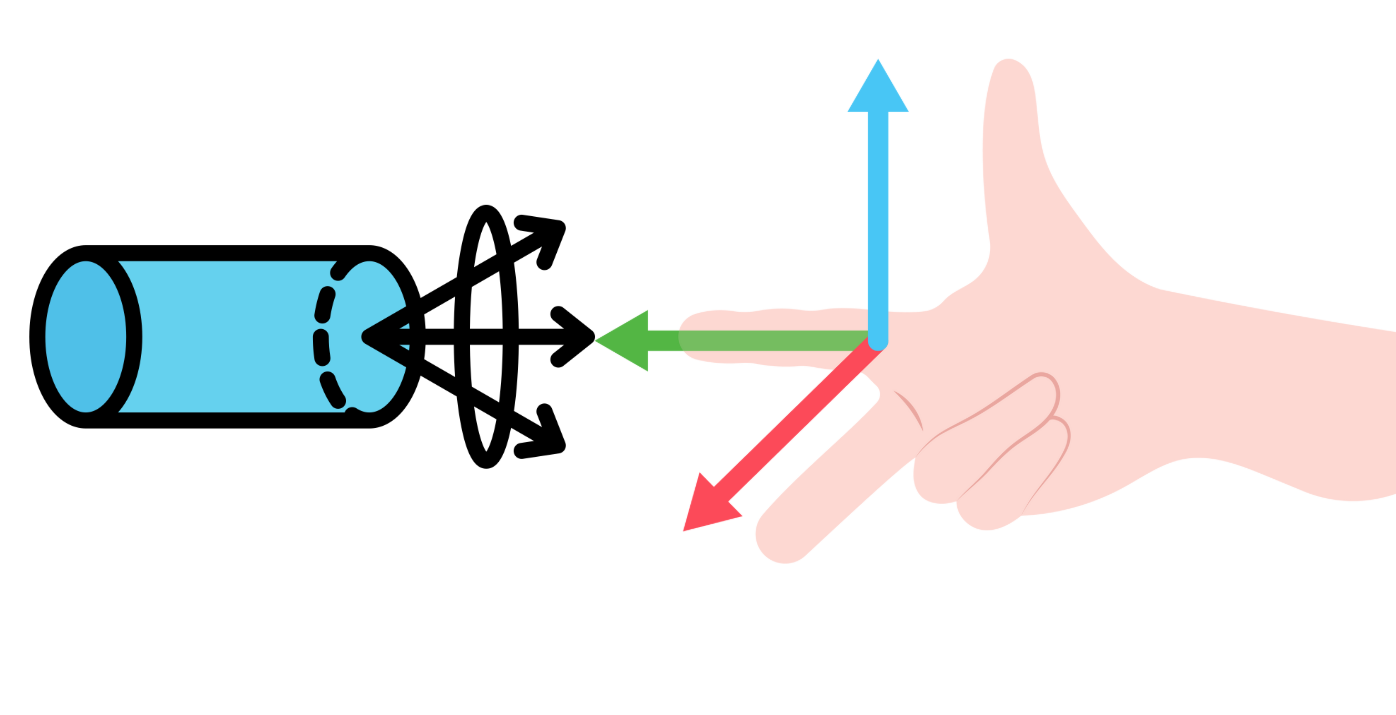
- Lenz law shortcut: Use the right‑hand rule – thumb along the change (field direction), fingers give current direction that opposes the change.
- ELI the ICE man: In an L (inductor) E (voltage) leads I (current); in a C (capacitor) I leads E.
- At resonance, remember “Z = R” and current is maximum. It’s like a purely resistive circuit.
- For transformers, power input = power output only for ideal. In reality, account for losses (eddy currents, hysteresis).
- In numericals, always check if values are peak or RMS – most AC sources give RMS.
📊 Comparison: Pure R, L, C in AC Circuits
| Element | Phase relation | Reactance/Resistance | Power factor (cos φ) |
|---|---|---|---|
| Resistor (R) | V & I in phase | R | 1 (unity) |
| Inductor (L) | V leads I by 90° | XL = ωL | 0 (lagging) |
| Capacitor (C) | V lags I by 90° | XC = 1/(ωC) | 0 (leading) |
❓ Frequently Asked Questions (NEET)
Q1: Why is there a negative sign in Faraday’s law?
The negative sign is the mathematical expression of Lenz’s law – it indicates that the induced EMF opposes the change in flux.
Q2: What is the significance of RMS value?
RMS value gives the equivalent DC value that would produce the same heating effect in a resistor. It’s used for power calculations in AC circuits.
Q3: How does a transformer work?
A transformer works on mutual induction. AC in the primary coil creates a changing magnetic flux, which induces an EMF in the secondary coil.
Q4: What is the condition for resonance in an LCR circuit?
Resonance occurs when XL = XC, i.e., ω = 1/√(LC). At this frequency, impedance is minimum and current is maximum.
Q5: How can I quickly find the direction of induced current?
Use Lenz’s law: the current creates a magnetic field that opposes the original change. Apply the right‑hand thumb rule accordingly.
Q6: What are eddy currents and how can they be reduced?
Eddy currents are loops of current induced in bulk conductors by changing magnetic fields. They cause heating losses. They are reduced by laminating the core (thin insulated sheets).
Q7: Is the formula ε = –L(dI/dt) valid for AC?
Yes, it applies instantaneously for any time‑varying current, including AC. For sinusoidal AC, it gives the induced EMF as a cosine function.
Q8: What is the quality factor (Q) in an LCR circuit?
Q factor measures the sharpness of resonance. It is given by Q = (1/R)√(L/C). A higher Q means narrower bandwidth and greater selectivity.
🎯 Final Takeaway
Electromagnetic Induction and AC is a high‑scoring chapter if you master the interplay between magnetism and electricity. Focus on understanding Lenz’s law (direction), the phasor approach for AC circuits, and the resonance condition. Practice at least 30–40 numericals from each sub‑topic, and you’ll find NEET questions straightforward. Remember: conceptual clarity + regular problem solving = success. Good luck!